:::: MENU ::::

Thursday, December 28, 2023

Bluetooth is a short-range wireless communication technology primarily used for data transmission and connectivity between digital devices. It was developed by an organization called the Bluetooth Special Interest Group (SIG), which includes companies from various industries.

The Main Features of Bluetooth:

Bluetooth technology is continually evolving, with each new version introducing improvements and new features.

  1. Short-Range Communication:
    Bluetooth technology is designed for short-range communication, typically within a range of 10 meters (approximately 33 feet). Some versions of Bluetooth can achieve longer communication ranges.

  2. Low Power Consumption:
    Bluetooth technology is designed for low-power communication, making it suitable for mobile devices such as smartphones, tablets, wearable devices, and other Internet of Things (IoT) devices.

  3. Data Transmission:
    Bluetooth can be used to transmit various types of data, including audio, images, documents, and other multimedia content.

  4. Multi-Device Connectivity:
    Bluetooth technology supports simultaneous connections to multiple devices. This multi-device connectivity makes Bluetooth very useful in a multi-device environment.

  5. Versatility:
    Bluetooth is a universal standard widely applied in various devices, including headphones, audio devices, keyboards, mice, printers, in-car systems, and more.

  6. Security:
    Bluetooth technology has certain security features, including encryption and authentication mechanisms, to ensure the security of communication.

The Bluetooth Version History:


The progression of Bluetooth technology continues to advance, and future versions may bring further improvements. The application scope of Bluetooth technology is expanding from traditional audio and data transmission to areas such as the Internet of Things, automotive systems, and smart homes.

Bluetooth technology undergoes continuous updates, with Bluetooth 5.4 being the latest version, while previous versions include Bluetooth 5.0, Bluetooth 4.2, Bluetooth 4.0, and so on.


Bluetooth 5.0:
Launched in 2016, it provided a longer range, faster data transfer rates, and improved connection density. It also introduced Mesh network support, allowing Bluetooth devices to form large networks.

Bluetooth 5.1:
Released in 2019, it introduced directional Bluetooth signals, improving the accuracy of location positioning.

Bluetooth 5.2:
Also released in 2019, it introduced LE Audio, providing better audio performance and multi-stream audio capabilities.

Bluetooth 5.3:
Released in 2020, it further improved positioning technology and range.

Bluetooth 5.4:
Released in 2023, facilitating secure bidirectional communication between wireless Access Points (AP) and ultra-low-power terminal nodes.


The Most Widely Adopted Bluetooth 5.0


Booth Logo

  1. Maturity and Adoption:
    Bluetooth 5.0 is a relatively mature and widely deployed technology that has found applications in various devices, including smartphones, headphones, and speakers. This widespread adoption may make Bluetooth 5.0 more readily accepted, given its established presence in the market.

  2. Compatibility:
    Bluetooth 5.0 has higher compatibility relative to earlier versions, seamlessly working with older Bluetooth devices. This is an advantage in scenarios where a variety of different Bluetooth devices are in use.

  3. Cost:
    Generally, the hardware and related devices for Bluetooth 5.0 may be more cost-effective. If cost is a significant consideration, Bluetooth 5.0 could be a more practical choice.

  4. Application Support:
    Currently, many applications and devices predominantly support Bluetooth 5.0, and the support for Bluetooth 5.3 may be relatively limited. This could be a crucial consideration when choosing the appropriate hardware and software ecosystem.
MAS1011 / MAA1013MAS1011 / MAA1013


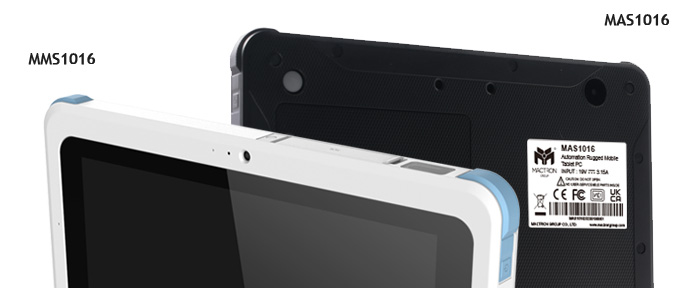
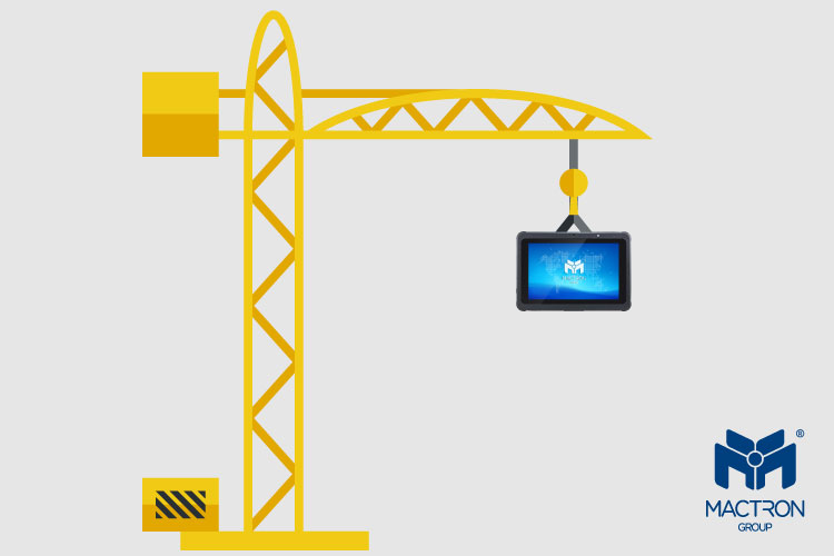
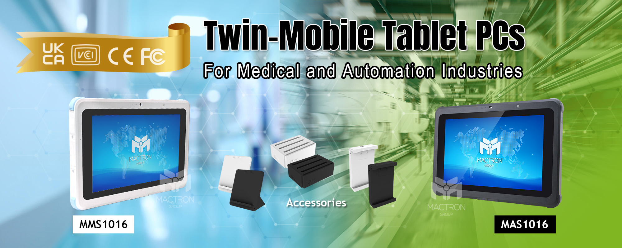
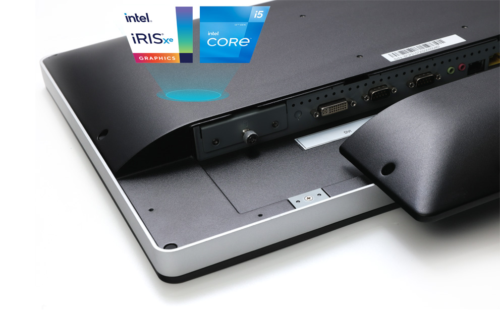
Check out MACTRON GROUP(MTG)’s MAS Series/ MAA Series Series. Our mobile tablets are all equipped with Bluetooth 5.0 and Bluetooth 5.2, which can meet your work environment and connected devices.

Tuesday, October 31, 2023


The principle of a capacitive touch screen

A touch screen is an input device that allows users to interact with a device by directly touching the screen. There are two common types of touchscreen technologies:

Resistive Touch Screen: A resistive touch screen consists of two layers of flexible transparent resistive film. When the screen is pressed by a finger or stylus, it generates pressure at the touch point, causing the two layers of resistive film to make contact and form a circuit. The touch panel detects the pressure and position information and sends it to the processor for processing.

Capacitive Touch Screen (PCAP): A capacitive touch screen uses sensing electrodes to create an electric field on the screen. When a finger touches the screen, it changes the distribution of the electric field, which is detected by the sensing electrodes and converted into touch position information. Capacitive touch screens are divided into surface capacitance and projected capacitance types.


The advantages of PCAP touch screens

The reason why MACTRON GROUP computers are equipped with PCAP touch screens is because PCAP touch screens have the following advantages over resistive touch screens:

Multi-touch Capability:
PCAP touch screens can detect and track the positions and movements of multiple touch points simultaneously, supporting multi-finger gestures. This enables users to engage in more interactive experiences, such as pinch-to-zoom, rotation, and gesture controls.

Higher Precision and Accuracy:
PCAP touch screens detect touch positions by measuring changes in capacitance, rather than just pressure changes. Due to this principle, PCAP touch screens typically have higher precision and accuracy, enabling more precise touch operations.


Strong Interference Resistance:
PCAP touch screens have good anti-static interference capabilities, allowing them to accurately identify touch signals without being affected by external noise and interference. This enables stable touch operations in various environmental conditions.

Good Transparency:
The sensing electrodes of PCAP touch screens are made of transparent materials, which do not significantly affect the display effect of the screen, maintaining good visual quality. This makes touch screens more versatile in design, suitable for displays of various sizes and shapes.

Durability:
PCAP touch screens are typically composed of durable glass panels and electrode structures, providing high durability and scratch-resistant performance. This makes PCAP touch screens suitable for long-term, frequent use, and resistant to scratches or damage that may occur during daily use. In summary, PCAP touch screens have advantages over resistive touch screens in terms of multi-touch capability, high sensitivity and instant responsiveness, higher precision and accuracy, interference resistance, transparency, and durability. These advantages make PCAP touch screens a common and popular touch technology in modern devices.

Choose a PCAP touch Panel PC

In summary, PCAP touch screens have advantages over resistive touch screens in terms of multi-touch capability, higher precision and accuracy, interference resistance, transparency, and durability. These advantages make PCAP touch screens a common and popular touch technology in modern devices.

WCP Series

Check out MACTRON GROUP(MTG)’s WCP/ WMP Series. Our Premium Touch Panel PC comes in two different sizes, featuring exceptional performance and an exquisite chassis, along with a PCAP capacitive touch screen. It can meet all your imagination.

Thursday, September 28, 2023


In the era of advancing technology, wireless communication technologies are continually evolving and playing a pivotal role in various industries. Among these, RFID (Radio-Frequency Identification) and NFC (Near Field Communication) are two intriguing technologies, and their applications in the IPC (Interconnect Printed Circuit) industry are noteworthy. This article will introduce the characteristics of RFID and NFC frequencies and explore the applications of UHF RFID in the IPC industry.

RFID Frequency Bands and Their Relation to NFC


  1. Low Frequency (LF):
    Frequency Range: 125 kHz to 134.2 kHz.
    Characteristics: LF RFID systems are typically used for close-range identification applications with shorter reading ranges and slower communication speeds. These systems have good resistance to interference from metals and liquids, making them suitable for applications like animal tagging and access control.

  2. High Frequency (HF):
    Frequency Range: 13.56 MHz.
    Characteristics: HF RFID systems have longer reading ranges and faster communication speeds. They are commonly used for near-field identification applications such as smart cards, library management, and payment systems.

  3. Ultra High Frequency (UHF):
    Frequency Range: 860 MHz to 960 MHz.
    Characteristics: UHF RFID systems offer very long reading ranges and the ability to read multiple tags simultaneously. They are widely used in logistics, supply chain management, inventory tracking, and the retail industry.

  4. Microwave Frequencies:
    Frequency Range: 2.45 GHz, 5.8 GHz, and others.
    Characteristics: Microwave RFID systems are used for specific applications like highway toll collection, aircraft parts tracking, and medical equipment tracking. They typically have higher reading ranges and communication speeds.

  5. NFC (Near Field Communication):
    Frequency Range: 13.56 MHz (same as HF RFID).
    Characteristics: NFC is a short-range communication technology based on RFID, commonly used in smartphones, smart cards, access systems, and payment applications. NFC allows devices to communicate and exchange data at very close distances, typically not exceeding 10 centimeters. NFC technology is built upon the HF RFID standard, so they share similarities.

Application of UHF RFID in the IPC Industry


Application of UHF RFID in the IPC Industry UHF RFID (Ultra High-Frequency Radio-Frequency Identification) plays a significant role in the IPC (Interconnect Printed Circuit) industry, enhancing production efficiency, quality control, and asset management. Below are some key applications of UHF RFID in the IPC industry:
  1. Production Tracking and Control:
    UHF RFID can be used to track the manufacturing process of printed circuit boards. Each printed circuit board can be equipped with a UHF RFID tag that is read throughout the manufacturing process. This allows for real-time production tracking, ensuring that each step is carried out as planned and tracking the production status.

  2. Inventory Management:
    IPC manufacturers often deal with large inventories, including raw materials, finished products, and components. Using UHF RFID tags enables automated inventory management, including inventory tracking, stocktaking, and replenishment. This helps reduce inventory losses and improves inventory accuracy.

  3. Quality Control:
    UHF RFID can be utilized to track quality data for printed circuit boards. Tags on each board can contain relevant quality data such as production dates, test results, and inspection records. This helps ensure that products meet quality standards and tracks any potential quality issues.

  4. Asset Management:
    IPC manufacturers possess a significant number of production equipment and tools. Using UHF RFID tags enables effective management and tracking of these assets. This includes recording the location, status, and maintenance records of equipment to ensure they are in optimal working condition.

  5. Anti-Counterfeiting and Traceability:
    UHF RFID tags can be used to prevent counterfeiting and trace products. This is crucial for the IPC industry, which adheres to high standards and regulations. Each printed circuit board can have a unique identifier, ensuring its authenticity and allowing for the tracking of product origins and history records.

Overall

In summary, UHF RFID technology provides effective tools for production tracking, inventory management, quality control, and asset management in the IPC industry. It helps improve production efficiency, reduce costs, enhance quality, and ensure compliance with industry standards and regulations. These applications enable IPC manufacturers to better manage their production processes and deliver higher-quality products.


Check out MACTRON GROUP(MTG)’s MCA Series. Our Commercial Grade Android Mobile Tablet PC. Our UHF RFID has a maximum reading distance of 15 meters. Whether you are in the warehousing industry, logistics industry, or even a jeweler, this can definitely be a weapon for your business.

Wednesday, August 30, 2023


Warehouse management has always been a critical link in the logistics chain, directly impacting the storage, transportation, and distribution of goods. However, with the rapid advancement of technology, we are witnessing a revolution in the field of warehouse management, where volume measurement and ToF (Time of Flight) technology play a crucial role, bringing new possibilities to warehouse management.

Volume Measurement: Insights Beyond Surface


In traditional warehouse management, the volume of items is often handled with estimated or approximate values, which can lead to wastage of storage space and decreased transportation efficiency. However, through volume measurement technology, we are able to gain a deeper understanding of the actual volume of each item, enabling more precise storage and layout arrangements to optimize the utilization of warehouse space.

ToF Principle: The Technological Ally of Warehouse


ToF technology is becoming a powerful ally in warehouse management. It measures the distance of objects based on the speed of light propagation, enabling rapid and accurate measurements of items for precise warehouse management. Specifically, ToF technology helps us quickly determine the volume of each item, optimizing storage, transportation, and distribution processes.

Applications of ToF Technology in Warehouse Management


Goods Storage:

Using ToF technology, warehouse managers can quickly measure the volume of each item, determining the optimal storage location and stacking method for maximizing space utilization.

Transportation Optimization:

During the transportation process, ToF technology can help determine the efficient utilization of transport containers, reducing space wastage and enhancing transportation efficiency.

Inventory Management:

Regularly measuring the volume of individual items in inventory, warehouse managers can achieve more accurate inventory management, minimizing situations of excess or insufficient stock.

Future Prospects: Technology Empowering the Future of Warehousing

Volume measurement is sparking a revolution in the field of warehouse management and reshaping our perspective on it. The application of this technology will bring more efficient and precise management methods to warehouse operations, simultaneously reducing costs and enhancing customer satisfaction. We can expect the field of warehouse management to become increasingly intelligent and efficient, presenting more opportunities and challenges for the future of the logistics industry.

MCA0556 without Volume Measurement Module (left) and with Volume Measurement Module (right).

Check out MACTRON GROUP(MTG)’s MCA Series. The MCA0556 in our Commercial Grade Android Mobile Tablet PC can be equipped with Volume Measurement, which can detect the goods in 40CM to 4M, and the error is less than 5%, which can definitely satisfy all your imagination for this application.

Monday, July 31, 2023


With the continuous development in the medical field, antimicrobial coatings are gaining increasing attention and application in various industries. However, there are different technologies of antimicrobial coatings available in the market, each with its unique advantages and limitations. In this article, we will delve into several common antimicrobial coating technologies and compare their differences to help you better understand and choose the most suitable antimicrobial coating.

Technologies of Antimicrobial Coatings


Silver Ion Technology:

Advantages:
  • Silver possesses powerful antimicrobial properties, effective against a wide range of bacteria and fungi.
  • Long-lasting antimicrobial effect, capable of maintaining surface hygiene over an extended period.
  • Applicable in various environments, such as medical facilities and food processing plants.
Disadvantages:
  • High cost, as silver ions are expensive materials.
  • Some bacteria may develop resistance to silver.
  • Further research is needed to determine its environmental impact.

Copper Ion Technology:

Advantages:
  • Copper exhibits strong antimicrobial properties, effectively combating bacteria.
  • Widely used in high-risk areas like medical facilities and public spaces.
  • Long-lasting antimicrobial effect without significant leaching.
Disadvantages:
  • Copper ion technology may have less effective antimicrobial properties against certain fungi.
  • Copper may undergo color changes or corrosion under certain circumstances.

Enzyme Technology:

Advantages:
  • Utilizes natural enzymes, environmentally friendly.
  • Antimicrobial coatings can inhibit the growth of various bacteria.
Disadvantages:
  • Antimicrobial effect may not be as significant as metal ion technologies.
  • Stability and activity of enzymes may be influenced by factors like temperature and pH.

Antimicrobial Agent Technology:

Advantages:
  • Generally cost-effective, widely used for general disinfection purposes.
  • Various types of antimicrobial agents available to meet different needs.
Disadvantages:
  • Some antimicrobial agents may have negative effects on human health and the environment.
  • Regular reapplication of coatings is necessary to maintain antimicrobial efficacy.

Our Antimicrobial Coatings


Our WMP series is a premium Panel PC designed specifically for medical applications. It utilizes an antimicrobial coating that incorporates zinc compounds, a new type of inorganic antimicrobial agent. This coating offers excellent corrosion resistance, color stability, and effectiveness against a wide range of bacteria and molds. Moreover, it demonstrates high heat resistance and safety for human contact.

Overall

The choice of antimicrobial coating technology should be based on specific application requirements and environmental conditions. Silver ion and copper ion technologies exhibit powerful antimicrobial effects, particularly suitable for high-risk areas. Enzyme technology offers environmental friendliness and a broad range of antibacterial inhibition. Antimicrobial agent technology is cost-effective and applicable for general disinfection needs.

When selecting antimicrobial coatings, factors such as cost, efficacy, durability, and environmental considerations should be taken into account. Additionally, regular cleaning and maintenance remain essential for maintaining hygiene. Please follow the manufacturer's recommendations and usage guidelines to ensure optimal antimicrobial efficacy.

We hope this article helps you gain a better understanding of the differences and pros and cons of antimicrobial coating technologies, enabling you to make informed decisions when choosing the right antimicrobial coating. Let's strive for cleanliness and hygiene to create safer and healthier environments!


Check out MACTRON GROUP(MTG)’s brand new WMP Series. Our Medical Premium Windows Touch Panel PC has 12th generation CPU and powerful performance, it can complete all the tasks you give it in the medical field, satisfying all your imagination.

Thursday, June 29, 2023


Hot swapping is the function of inserting or removing components or devices from electronic equipment while it is operational. This feature allows users to replace or upgrade hardware while the system is running without the need to shut down or restart the entire system. However, hot-swapping batteries is actually a very dangerous action that can easily damage the hardware if not properly protected. This article will discuss this issue in detail and provide solutions to eliminate circuit hazards and improve the reliability of product functionality.

The Perils of Hot Swapping


Hot swapping actions often cause significant current or voltage fluctuations. Voltage fluctuations occur because the inserted or removed component is in an unstable state when making contact with the circuit, while current fluctuations result from the capacitive characteristics of the component's low equivalent series resistance (ESR). Regarding voltage fluctuations, they can usually be compensated for in design by increasing energy storage devices, improving the circuit's voltage compatibility range, and other methods. However, protection against current fluctuations is often overlooked in engineering design. When hot-swapping modules with low ESR, the momentary circuit contact is equivalent to a short circuit to ground. In many applications, this momentary current can even reach several hundred amperes.

From this, it is evident that the risks of hot swapping primarily involve surge currents and oscillating voltages. As mentioned earlier, surge current is an exceptionally large instantaneous current caused by the presence of parasitic circuit parameters. Oscillating voltage occurs when surge currents appear on PCB traces, where even small impedance can cause significant voltage variations. The longer or thinner the traces, the greater the voltage amplitude.

In summary, we need to pay more attention to the issue of hot-swapping batteries due to the following reasons:
  • Batteries are one of the most common hot-swappable components, and we often instinctively hot-swap them.

  • Batteries have very low equivalent impedance, so once surge currents occur, they can be quite severe.

Methods to Protect Against Battery Hot Swap Damage


Protecting against surge currents requires taking measures at the source, which involves adding protection between the hot-swapping point and the backend circuitry. In some simple protection circuits, commonly used components include ferrite beads and magnetic rings. They can significantly suppress surge currents but may worsen oscillating voltages because they introduce inductance into the circuit, causing additional induced voltages. Currently, the more reliable method is to use complex components. In engineering design, there are two common types of surge current protection circuits: those constructed using discrete devices and those utilizing dedicated surge protection chips.

How About MTG's Hot Swap

Our WMR2387 uses the hot-swappable function, the two batteries have a total power of 13600mAh, and have passed CE, FCC, CB, UL60601-1 and other certifications, so that you can continue to use the product safely without plugging in the power , and replace the battery at any time.


Check out MACTRON GROUP(MTG)’s brand new WMR2387. Our Medical Rechargeable Touch Panel PC can show outstanding performance in any medical field, and provide you with safe and powerful services. It can meet all your imagination.

Wednesday, May 31, 2023


In this rapidly advancing digital era, we increasingly rely on wireless networks to connect with the world, with Wi-Fi (Wireless Fidelity) technology being the most common. But did you know that Wi-Fi has different grades based on speed and functionality? Let's delve into it!

What Is Wi-Fi?


Wi-Fi, short for Wireless Fidelity, is a wireless network technology that allows us to connect to the internet or other local area networks without any wired connections. It enables us to use wireless devices such as computers, smartphones, and tablets to access Wi-Fi networks. Wi-Fi uses radio waves to transmit data, allowing us to connect to Wi-Fi networks from anywhere within its coverage range without the need for network cables or being confined to a fixed location. It provides us with the convenience and enjoyment of accessing the internet more easily.

Evolution of Wi-Fi Levels


The evolution of Wi-Fi grading has witnessed significant advancements in speed, capacity, and functionality. Each generation has brought improvements to wireless networking, enabling faster and more reliable connections. Understanding the evolution of Wi-Fi helps us make informed decisions when choosing devices and optimizing our Wi-Fi experience.
  • Wi-Fi 1 (802.11b):
    Introduced in 1999, Wi-Fi 1 was one of the earliest wireless local area network (WLAN) standards. It operated in the 2.4 GHz frequency range and offered a maximum data transfer rate of 11 Mbps. Although slower compared to later standards, Wi-Fi 1 laid the foundation for wireless networking.

  • Wi-Fi 2 (802.11a)
    Also introduced in 1999, Wi-Fi 2 expanded the Wi-Fi market alongside Wi-Fi 1. It operated in the 5 GHz frequency range, providing a higher maximum data transfer rate of 54 Mbps. Wi-Fi 2 offered improved bandwidth and transmission performance.

  • Wi-Fi 3 (802.11g)
    Released in 2003, Wi-Fi 3 combined the features of Wi-Fi 1 and Wi-Fi 2. It operated in the 2.4 GHz frequency range, supporting a maximum data transfer rate of 54 Mbps. Wi-Fi 3 was backward compatible with Wi-Fi 1 and Wi-Fi 2, contributing to the widespread adoption of wireless networking.

  • Wi-Fi 4 (802.11n)
    Introduced in 2009, Wi-Fi 4 marked the fourth generation of WLAN technology. It supported both 2.4 GHz and 5 GHz frequency ranges, offering a maximum data transfer rate of 300 Mbps. Wi-Fi 4 provided improved signal penetration, coverage, and backward compatibility.

  • Wi-Fi 5 (802.11ac)
    Wi-Fi 5, launched in 2014, represented the fifth generation of WLAN technology. Operating solely in the 5 GHz frequency range, it offered a maximum data transfer rate of 1 Gbps. Wi-Fi 5 provided greater bandwidth and enhanced capability for simultaneous device connections, delivering superior network performance with lower latency.

  • Wi-Fi 6 (802.11ax)
    Wi-Fi 6, also known as High-Efficiency Wireless (HEW), was introduced in 2019 as the sixth generation of WLAN technology. It operates in both 2.4 GHz and 5 GHz frequency ranges, supporting a maximum data transfer rate of 10 Gbps. Wi-Fi 6 offers increased network capacity, improved simultaneous device connections, and better signal stability, along with lower power consumption.

Check out MACTRON GROUP(MTG)’s brand new MAS1016 & MMS1016. This Rugged Mobile Tablet PC support Wi-Fi 5 level WLAN technology. They are designed to support various applications in different fields, be it healthcare, industrial, or commercial. It can meet all your imagination.

Sunday, April 30, 2023


 The military drop test is a certification that many 3C products will have, especially in the industries, this certification is even one of the basic conditions. Let's take a deeper look at how it works.

4 Procedures In Certification


The drop testing section of MIL-STD-810G 516.6 includes several test methods and standards, such as Procedure I, Procedure IV, Procedure V, and Procedure VI. Each of these procedures is designed to simulate specific types of impact forces and environmental conditions, and the product being tested must pass all of the relevant tests to meet the standard's requirements.

Procedure I: This procedure involves dropping a product onto a flat, hard surface from various heights and angles, with the goal of simulating the impact forces that can occur when a product is dropped in normal use.

Procedure IV: This procedure simulates the impact forces that can occur when a product is dropped onto a hard surface while it is being transported or used.

Procedure V: This procedure involves dropping a product onto a hard surface while it is in operation, simulating the forces that can occur when a product is dropped during active use.

Procedure VI: This procedure simulates the impact forces that can occur when a product is dropped onto a hard surface while it is in storage, simulating the forces that can occur during transportation and storage.

Out-of-Procedure Inspection


In addition to the specific test procedures outlined in MIL-STD-810G, there are also general requirements for drop testing. For example, it must pass drop tests on 8 corners, 6 sides, and 12 sides, with the product fully operational and functional after each drop, and that the product be fully operational and functional after each drop. The standard also specifies the type of equipment and instrumentation required for drop testing, as well as the criteria for determining pass/fail results.

Overall, MIL-STD-810G's drop testing procedures are designed to ensure that military equipment can withstand the impact forces that can occur during transportation, storage, and use. By adhering to these testing procedures, manufacturers can ensure that their products meet the ruggedness and durability requirements of the military and other demanding applications.


Check out MACTRON GROUP(MTG)’s brand new MAS1016 & MMS1016. This Rugged Mobile Tablet PC can support applications in several different fields, whether in medical treatment, industry or business, it can perform quite well. It can meet all your imagination.

Friday, March 31, 2023


CAN (Controller Area Network) is a serial communication protocol used for communication between vehicles and other devices. It is a highly reliable, fast and energy-efficient communication protocol that has become standard in modern vehicles. With the development of cloud computing, IoT and autonomous driving, the impact of CAN bus is increasing. Now let's take a look at the system.

What is CAN bus?


In fact, our car is like a human body, and the CAN bus is like a nervous system, making communication possible. The "node" and "Electronic Control Unit" (ECU) are like parts of the body, connected to each other through the CAN bus.

In an automotive CAN bus system, ECUs can be the engine control unit, airbag, audio system and other functions. A modern car may have as many as 70-80 ECUs - each of them may have information that needs to be shared with other parts of the network.

How the CAN bus Works?

The CAN bus usually consists of two differential lines. One is CAN high and the other is CAN low. The two wires transfer data in a balanced manner to reduce noise and interference, and use a polling method to determine priority in the network. When multiple devices try to transmit data at the same time, CAN bus will assign the priority of data transmission to the most important data to ensure its priority transmission.

The Rise of CAN FD


As the functionality of the vehicle expands, so does the functionality of the CAN bus. In response to this, CAN FD is designed as the "next generation" CAN bus.

In general, CAN FD has three advantages (vs CAN 2.0):
  • It enables data rates up to 8 Mbit/s (vs 1 Mbit/s)
  • It allows data payloads of up to 64 bytes (vs 8 bytes)
  • It enables improved security via authentication
All in all, CAN FD improves the transmission speed and efficiency, so it is extended to new vehicles. This will also drive the growing demand for IoT CAN FD data loggers.

The Future of CAN bus


With the continuous advancement of technology, the development of CAN bus will inevitably be affected by major trends.

This includes increasingly advanced functional requirements, the rise of cloud computing, the combination of the IoT with smart cars and autonomous driving, etc., especially the rise of V2X and cloud computing, which has led to the rapid growth of automobile development.


Check out MACTRON GROUP(MTG)’s new MAV Series. Our Vehicle Mounted Mobile Tablet PC perfectly supports CAN bus 2.0, and with All-In-One Cable design. If your demand for can bus is in the automotive industry, then our MAV series will never let you down.

Friday, February 24, 2023


Terminal blocks are a fairly common part of an engineer's toolbox and have provided reliable wire connections in numerous applications for many years. The semi-fixed nature of the terminal block helps simplify inspection and repair operations.

Let's take a look at the terminal block

Three Types of Terminal Blocks


PCB Mount:

Usually called European gauge or wire-to-board terminal block, the configuration is mainly single-layer, double-layer or multi-layer, and the wire fixing method is to insert the bare wire into the module and then fix it to the outer cover.

Barrier Strips:

Commonly used in applications where vibration is a concern, the configuration is mostly to fix the terminals with screws, and the wire fixing method is mainly to insert bare wires or terminal wires into the screws and then lock them into the housing.

Feed-Through:

Used to splice two wires together to achieve a wire-to-wire connection, commonly found in DIN rail-mounted types. The wire fixing method is mainly to insert two wires into the two sides of the outer cover to form a connection.

A Selection Guide for Terminal Block

Current Rating:

The current rating is often the most important parameter to consider in terminal block designs. The current rating is based on the conductivity of the terminals, cross-sectional area, and the corresponding heat rise. Operating at too high of a current can cause overheating and damage of the terminal block, leading to major safety concerns. It is best practice to use a terminal block that is rated for at least 150% of the max current that is expected in the system.

Pitch:

A terminal block’s pitch is defined as the center distance from one pole to the next. The pitch of the connector is often determined by the overall rating of the terminal block where factors like voltage/current, creepage, and clearance are considered. Common industry pitches include 2.54 mm, 3.81 mm, 5.0 mm, and 7.62 mm.

Wire-Entry Orientation:

Horizontal (90°), vertical (180°) and 45° are the three most common terminal block orientations. The decision takes into account the layout of the design and the orientation that produces the best connection fit and accessibility.

Wire Securing Method:

The way in which the wires are secured in the terminal block housing are typically accomplished by three main types: Screw Terminal, Push Button and Push In.

Screw Terminal - The screw terminal secures the wire against the conductor in the terminal block by tightening a screw that closes the clamp.

Push Button - Push button terminal blocks secure the wire against the conductor by a spring clamp that is opened by pressing a button. Releasing the button clamps the spring onto the wire.

Push-In - Similar to the push button with a spring clamp, a push-in terminal block allows the wire to be pressed directly into the housing without the use of a push button to open the spring.

WAM applies to all industrialists


The terminal blocks used in our WAM series are divided into two sizes, 11 and 12 inches use 2-hole terminal blocks, and 15.6, 17 and 21.5 inches use 6-hole terminal blocks. The terminal block specifications are all single-layer, 3.81 mm pitch, vertical (180°) interface, current rating 8A, and screw terminal type terminal block.

This configuration is definitely one of your best choices in terms of security and operation.


Check out MACTRON GROUP(MTG)’s new WAM Series. Our Panel Mount Touch Panel PC can adapt to all kinds of work environments with powerful performance, and combine with the PCB Mount Terminal Block. It can meet all your imagination.

Friday, February 3, 2023

There are various types of video adapters, and VGA, DVI, HDMI, DP are the most popular. What are the differences between these four modes? Let us take a closer to find out the truth.

Veteran Screen Mode: VGA


Released: 1987
Also known as D-sub connector, VGA is composed of 15 pins, which is transmitted in the form of analog, which mainly divides the display signal into different types of signals and sends them to the display.

Limitations and Disadvantages of VGA

Generally, VGA may not be able to display images normally if it is more than 15 meters away, and the resolution support can only reach 1920×1080 @ 60 Hz. In addition, since VGA transmits analog, an additional DAC bit is required on the display card The signal is converted to analog, but the analog cannot preserve the color information of each pixel, so the picture quality is poor, especially on larger screens.

Entering the Digital Age: DVI

Released: 1999
VGA transmits analog signals, the reason is to match the CRT screen, but things have changed drastically after entering the era of LCD monitors. If you want to use VGA interface with LCD screen, you need to go through several signal conversions in the middle, so DVI was born.

Types of DVI

DVI may be the most complicated type among all video adapters. It is mainly divided into three categories and five different connector types. Among them, the three categories are DVI-D, which is fully digital, and DVI-A, which maintains analog signal compatibility. And DVI-I combines the characteristics of both.

Limitations and Disadvantages of DVI

The highest resolution of DVI in Single Link is 1920×1200 @ 60 Hz, and the highest resolution of Dual Link is 2560×1600 @ 60 Hz, which is only a little higher than 2K resolution. Moreover, the size of the DVI connector is too large. Generally, the display card can only accommodate two DVI connectors at most, which brings big trouble to the development of the display.

Universal Digitalization: HDMI


Released: 2003
What is special about HDMI is that in addition to video signals, HDMI can also transmit audio signals. After HDMI 1.3 version, it adds support for DTS-HD and Dolby TrueHD.

Types of HDMI

HDMI can be divided into five different connector types, namely Type A to E. Type A, C, and D are only different in size, the transmitted content is consistent, so they can be converted to each other. Type B is the Type A corresponding to the DVI Dual Link version. It is very similar to Type A in appearance but wider. Type E is the version for automotive electronics.

Limitations and Disadvantages of HDMI

The most criticized thing about HDMI is that there are a bunch of versions, even the transmission lines are distinguished. The previous version was not much different. The difference is obvious after version 1.3. 1.4 supports 3D images and 1080 resolution at 120 Hz. The 2.0 version can stably support 4K resolution 60 Hz.

HDMI cable identification

HDMI STANDARD

The cable with this mark belongs to the HDMI 1.4 standard version, which cannot support 1080p resolution and can only support up to 1080i resolution.

HDMI HIGH SPEED

The cable with this mark belongs to HDMI 1.4 high-speed version, which can support 1080p and 2K, 4 resolution and 3D picture.

HDMI PREMIUM

This kind of mark only appears on the HDMI 2.0 cable, which can support up to 4K @ 60 Hz images. This type of cable must be tested by the HDMI organization and will be issued after passing the test. Due to additional certification fees, such cables are particularly expensive.

The DVI's Successor: DisplayPort

Released: 2006
DisplayPort is a relatively new specification. Overall, its characteristics are similar to HDMI. However, DisplayPort abandons the TMDS technology used in DVI and HDMI in the past and uses LVDS instead. It uses a packet technology similar to Ethernet to transmit data. The benefit of using the packet method is that DisplayPort can achieve the function of a single interface corresponding to several independent devices through a hub, which makes a breakthrough in the development of multi-screen architecture.

Limitations and Disadvantages of DisplayPort

The initial 1.0 version can support a transmission rate of 8.64 Gbps, but the limitation is that the transmission line is only up to 2 meters long. The new 1.3 and 1.4 versions can support a maximum resolution of 4K or even 8K, but the 8K resolution with a 60 Hz update frequency requires version 1.4 with Display Stream Compression technology to achieve.

What We Use on the WCP & WMP Series?


Our WCP/WMP series uses HDMI 2.0 that can support 4K / 60 Hz and DVI-I mode which supports 2560×1600 / 60 Hz, and this year we also upgraded the CPU to the Intel 12th generation. Such specifications must not be missed.

Check out MACTRON GROUP(MTG)’s new WCP Series and WMP Series. Our WCP Series will replace the processor from 8th Gen to 12th Gen early next year, which can perfectly fit all the specification upgrades of the 12th Gen processor. Take a look at this series, maybe there will be unexpected gains for you.