:::: MENU ::::

Sunday, April 30, 2023


 The military drop test is a certification that many 3C products will have, especially in the industries, this certification is even one of the basic conditions. Let's take a deeper look at how it works.

4 Procedures In Certification


The drop testing section of MIL-STD-810G 516.6 includes several test methods and standards, such as Procedure I, Procedure IV, Procedure V, and Procedure VI. Each of these procedures is designed to simulate specific types of impact forces and environmental conditions, and the product being tested must pass all of the relevant tests to meet the standard's requirements.

Procedure I: This procedure involves dropping a product onto a flat, hard surface from various heights and angles, with the goal of simulating the impact forces that can occur when a product is dropped in normal use.

Procedure IV: This procedure simulates the impact forces that can occur when a product is dropped onto a hard surface while it is being transported or used.

Procedure V: This procedure involves dropping a product onto a hard surface while it is in operation, simulating the forces that can occur when a product is dropped during active use.

Procedure VI: This procedure simulates the impact forces that can occur when a product is dropped onto a hard surface while it is in storage, simulating the forces that can occur during transportation and storage.

Out-of-Procedure Inspection


In addition to the specific test procedures outlined in MIL-STD-810G, there are also general requirements for drop testing. For example, it must pass drop tests on 8 corners, 6 sides, and 12 sides, with the product fully operational and functional after each drop, and that the product be fully operational and functional after each drop. The standard also specifies the type of equipment and instrumentation required for drop testing, as well as the criteria for determining pass/fail results.

Overall, MIL-STD-810G's drop testing procedures are designed to ensure that military equipment can withstand the impact forces that can occur during transportation, storage, and use. By adhering to these testing procedures, manufacturers can ensure that their products meet the ruggedness and durability requirements of the military and other demanding applications.


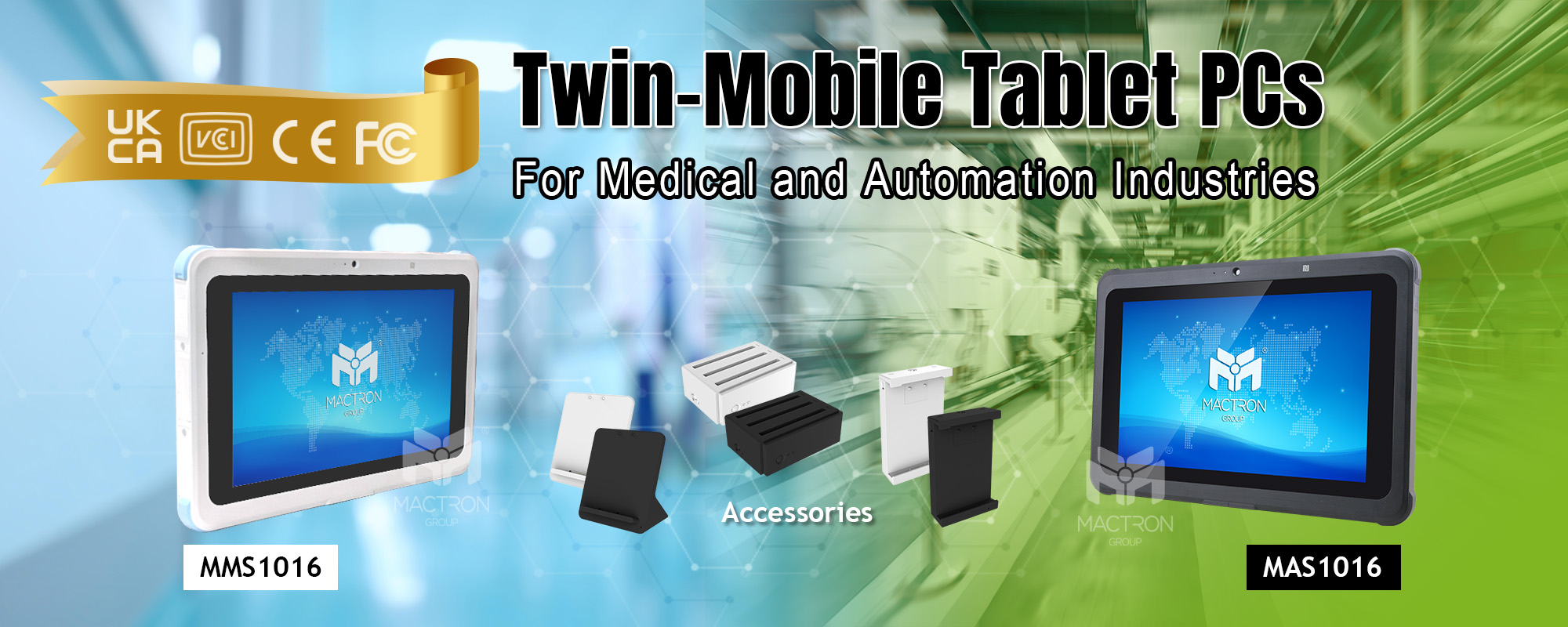
Check out MACTRON GROUP(MTG)’s brand new MAS1016 & MMS1016. This Rugged Mobile Tablet PC can support applications in several different fields, whether in medical treatment, industry or business, it can perform quite well. It can meet all your imagination.

Friday, March 31, 2023


CAN (Controller Area Network) is a serial communication protocol used for communication between vehicles and other devices. It is a highly reliable, fast and energy-efficient communication protocol that has become standard in modern vehicles. With the development of cloud computing, IoT and autonomous driving, the impact of CAN bus is increasing. Now let's take a look at the system.

What is CAN bus?


In fact, our car is like a human body, and the CAN bus is like a nervous system, making communication possible. The "node" and "Electronic Control Unit" (ECU) are like parts of the body, connected to each other through the CAN bus.

In an automotive CAN bus system, ECUs can be the engine control unit, airbag, audio system and other functions. A modern car may have as many as 70-80 ECUs - each of them may have information that needs to be shared with other parts of the network.

How the CAN bus Works?

The CAN bus usually consists of two differential lines. One is CAN high and the other is CAN low. The two wires transfer data in a balanced manner to reduce noise and interference, and use a polling method to determine priority in the network. When multiple devices try to transmit data at the same time, CAN bus will assign the priority of data transmission to the most important data to ensure its priority transmission.

The Rise of CAN FD


As the functionality of the vehicle expands, so does the functionality of the CAN bus. In response to this, CAN FD is designed as the "next generation" CAN bus.

In general, CAN FD has three advantages (vs CAN 2.0):
  • It enables data rates up to 8 Mbit/s (vs 1 Mbit/s)
  • It allows data payloads of up to 64 bytes (vs 8 bytes)
  • It enables improved security via authentication
All in all, CAN FD improves the transmission speed and efficiency, so it is extended to new vehicles. This will also drive the growing demand for IoT CAN FD data loggers.

The Future of CAN bus


With the continuous advancement of technology, the development of CAN bus will inevitably be affected by major trends.

This includes increasingly advanced functional requirements, the rise of cloud computing, the combination of the IoT with smart cars and autonomous driving, etc., especially the rise of V2X and cloud computing, which has led to the rapid growth of automobile development.


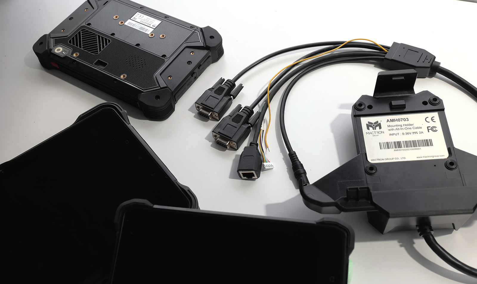
Check out MACTRON GROUP(MTG)’s new MAV Series. Our Vehicle Mounted Mobile Tablet PC perfectly supports CAN bus 2.0, and with All-In-One Cable design. If your demand for can bus is in the automotive industry, then our MAV series will never let you down.

Friday, February 24, 2023


Terminal blocks are a fairly common part of an engineer's toolbox and have provided reliable wire connections in numerous applications for many years. The semi-fixed nature of the terminal block helps simplify inspection and repair operations.

Let's take a look at the terminal block

Three Types of Terminal Blocks


PCB Mount:

Usually called European gauge or wire-to-board terminal block, the configuration is mainly single-layer, double-layer or multi-layer, and the wire fixing method is to insert the bare wire into the module and then fix it to the outer cover.

Barrier Strips:

Commonly used in applications where vibration is a concern, the configuration is mostly to fix the terminals with screws, and the wire fixing method is mainly to insert bare wires or terminal wires into the screws and then lock them into the housing.

Feed-Through:

Used to splice two wires together to achieve a wire-to-wire connection, commonly found in DIN rail-mounted types. The wire fixing method is mainly to insert two wires into the two sides of the outer cover to form a connection.

A Selection Guide for Terminal Block

Current Rating:

The current rating is often the most important parameter to consider in terminal block designs. The current rating is based on the conductivity of the terminals, cross-sectional area, and the corresponding heat rise. Operating at too high of a current can cause overheating and damage of the terminal block, leading to major safety concerns. It is best practice to use a terminal block that is rated for at least 150% of the max current that is expected in the system.

Pitch:

A terminal block’s pitch is defined as the center distance from one pole to the next. The pitch of the connector is often determined by the overall rating of the terminal block where factors like voltage/current, creepage, and clearance are considered. Common industry pitches include 2.54 mm, 3.81 mm, 5.0 mm, and 7.62 mm.

Wire-Entry Orientation:

Horizontal (90°), vertical (180°) and 45° are the three most common terminal block orientations. The decision takes into account the layout of the design and the orientation that produces the best connection fit and accessibility.

Wire Securing Method:

The way in which the wires are secured in the terminal block housing are typically accomplished by three main types: Screw Terminal, Push Button and Push In.

Screw Terminal - The screw terminal secures the wire against the conductor in the terminal block by tightening a screw that closes the clamp.

Push Button - Push button terminal blocks secure the wire against the conductor by a spring clamp that is opened by pressing a button. Releasing the button clamps the spring onto the wire.

Push-In - Similar to the push button with a spring clamp, a push-in terminal block allows the wire to be pressed directly into the housing without the use of a push button to open the spring.

WAM applies to all industrialists


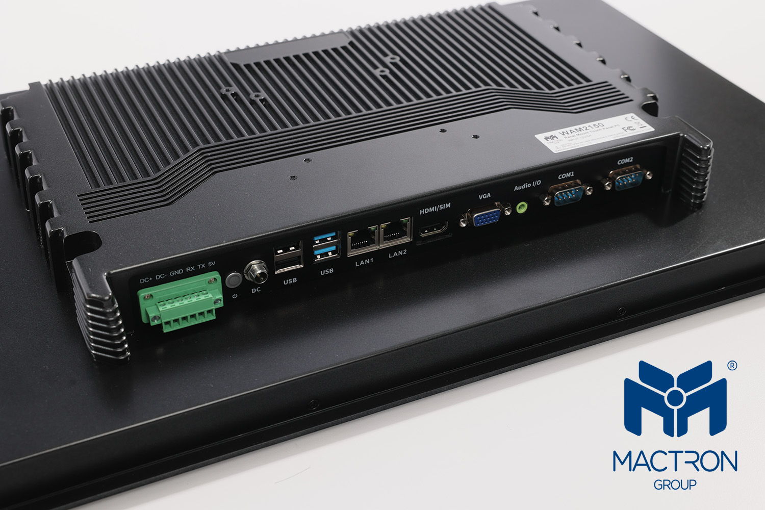
The terminal blocks used in our WAM series are divided into two sizes, 11 and 12 inches use 2-hole terminal blocks, and 15.6, 17 and 21.5 inches use 6-hole terminal blocks. The terminal block specifications are all single-layer, 3.81 mm pitch, vertical (180°) interface, current rating 8A, and screw terminal type terminal block.

This configuration is definitely one of your best choices in terms of security and operation.


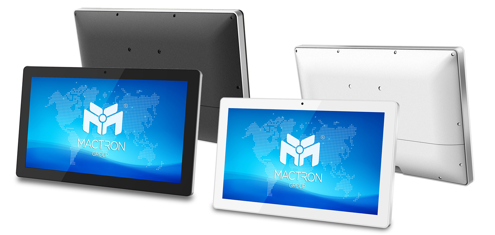
Check out MACTRON GROUP(MTG)’s new WAM Series. Our Panel Mount Touch Panel PC can adapt to all kinds of work environments with powerful performance, and combine with the PCB Mount Terminal Block. It can meet all your imagination.

Friday, February 3, 2023

There are various types of video adapters, and VGA, DVI, HDMI, DP are the most popular. What are the differences between these four modes? Let us take a closer to find out the truth.

Veteran Screen Mode: VGA


Released: 1987
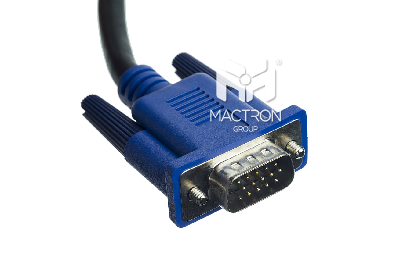
Also known as D-sub connector, VGA is composed of 15 pins, which is transmitted in the form of analog, which mainly divides the display signal into different types of signals and sends them to the display.

Limitations and Disadvantages of VGA

Generally, VGA may not be able to display images normally if it is more than 15 meters away, and the resolution support can only reach 1920×1080 @ 60 Hz. In addition, since VGA transmits analog, an additional DAC bit is required on the display card The signal is converted to analog, but the analog cannot preserve the color information of each pixel, so the picture quality is poor, especially on larger screens.

Entering the Digital Age: DVI

Released: 1999
VGA transmits analog signals, the reason is to match the CRT screen, but things have changed drastically after entering the era of LCD monitors. If you want to use VGA interface with LCD screen, you need to go through several signal conversions in the middle, so DVI was born.

Types of DVI

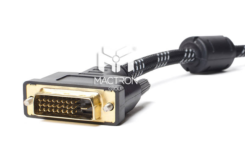
DVI may be the most complicated type among all video adapters. It is mainly divided into three categories and five different connector types. Among them, the three categories are DVI-D, which is fully digital, and DVI-A, which maintains analog signal compatibility. And DVI-I combines the characteristics of both.

Limitations and Disadvantages of DVI

The highest resolution of DVI in Single Link is 1920×1200 @ 60 Hz, and the highest resolution of Dual Link is 2560×1600 @ 60 Hz, which is only a little higher than 2K resolution. Moreover, the size of the DVI connector is too large. Generally, the display card can only accommodate two DVI connectors at most, which brings big trouble to the development of the display.

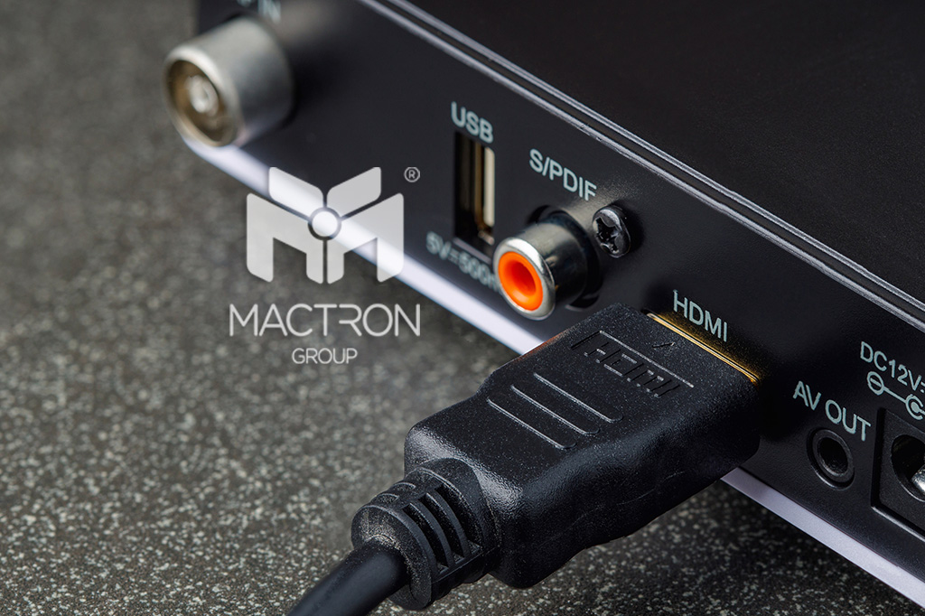
Universal Digitalization: HDMI


Released: 2003
What is special about HDMI is that in addition to video signals, HDMI can also transmit audio signals. After HDMI 1.3 version, it adds support for DTS-HD and Dolby TrueHD.

Types of HDMI

HDMI can be divided into five different connector types, namely Type A to E. Type A, C, and D are only different in size, the transmitted content is consistent, so they can be converted to each other. Type B is the Type A corresponding to the DVI Dual Link version. It is very similar to Type A in appearance but wider. Type E is the version for automotive electronics.

Limitations and Disadvantages of HDMI

The most criticized thing about HDMI is that there are a bunch of versions, even the transmission lines are distinguished. The previous version was not much different. The difference is obvious after version 1.3. 1.4 supports 3D images and 1080 resolution at 120 Hz. The 2.0 version can stably support 4K resolution 60 Hz.

HDMI cable identification

HDMI STANDARD

The cable with this mark belongs to the HDMI 1.4 standard version, which cannot support 1080p resolution and can only support up to 1080i resolution.

HDMI HIGH SPEED

The cable with this mark belongs to HDMI 1.4 high-speed version, which can support 1080p and 2K, 4 resolution and 3D picture.

HDMI PREMIUM

This kind of mark only appears on the HDMI 2.0 cable, which can support up to 4K @ 60 Hz images. This type of cable must be tested by the HDMI organization and will be issued after passing the test. Due to additional certification fees, such cables are particularly expensive.

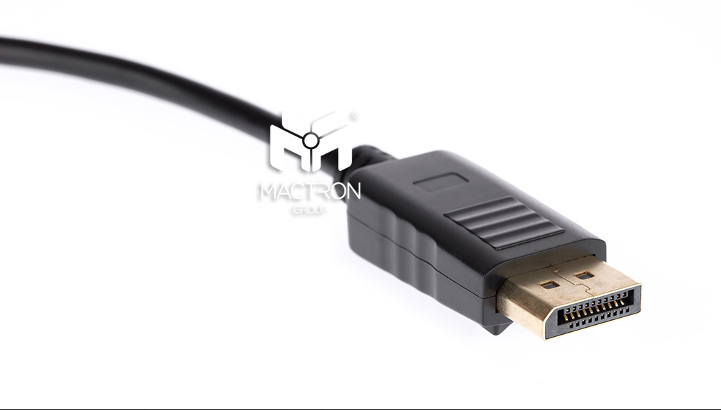
The DVI's Successor: DisplayPort

Released: 2006
DisplayPort is a relatively new specification. Overall, its characteristics are similar to HDMI. However, DisplayPort abandons the TMDS technology used in DVI and HDMI in the past and uses LVDS instead. It uses a packet technology similar to Ethernet to transmit data. The benefit of using the packet method is that DisplayPort can achieve the function of a single interface corresponding to several independent devices through a hub, which makes a breakthrough in the development of multi-screen architecture.

Limitations and Disadvantages of DisplayPort

The initial 1.0 version can support a transmission rate of 8.64 Gbps, but the limitation is that the transmission line is only up to 2 meters long. The new 1.3 and 1.4 versions can support a maximum resolution of 4K or even 8K, but the 8K resolution with a 60 Hz update frequency requires version 1.4 with Display Stream Compression technology to achieve.

What We Use on the WCP & WMP Series?


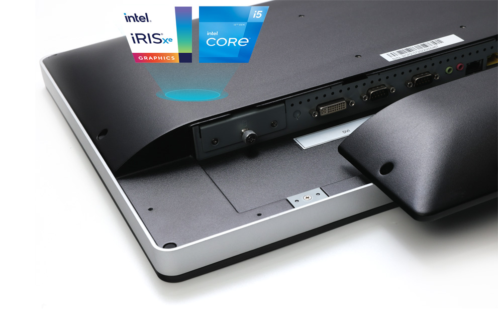
Our WCP/WMP series uses HDMI 2.0 that can support 4K / 60 Hz and DVI-I mode which supports 2560×1600 / 60 Hz, and this year we also upgraded the CPU to the Intel 12th generation. Such specifications must not be missed.

Check out MACTRON GROUP(MTG)’s new WCP Series and WMP Series. Our WCP Series will replace the processor from 8th Gen to 12th Gen early next year, which can perfectly fit all the specification upgrades of the 12th Gen processor. Take a look at this series, maybe there will be unexpected gains for you.

Friday, December 30, 2022


With the release of Intel's 12th Gen processors in 2022, people from all walks of life say that this is the biggest change in the past 15 years. All brands have successively upgraded their products, whether they are commercial computers or industrial computers.

Let's take a look at what substantial progress has been made in this processor.

Hybrid Architecture of P-Core & E-Core


There is a big innovation of the 12th Gen processors is the design of "Hybrid Architecture". Intel calls this a new breakthrough for the x86 processor, allowing a single processor to have the ability to "configure resources on demand".

Using the combination of "Performance core (P-core)" and "Efficient core (E-core), the former is designed for high-performance computing and has a maximum of 8 cores and 16 threads; the latter emphasizes low power consumption and power saving, with a maximum of 8 cores and 8 threads, making the processor more powerful.

Recognition Technology with Iris Xe Graphics

One of the biggest advancements in 12th Gen processors is Intel Iris Xe graphics. The importance of them is beyond what you might think at first glance. There is Deep Link technology embedded in there that let CPUs and GPUs run AI-powered applications at blazing speed without compromising the user experience.

They have integrated Deep Link technology into Gigapixel AI* application, upscaling images up to 6X with AI adding detail, clarity and improved speed when processing multiple images, and in the transmission process such as HDMI and DP, the graphics can reach 4K or even 8K pixels. It has also led to a huge growth in recognition technology.

A New Tech that Perfectly Fits with Win 11


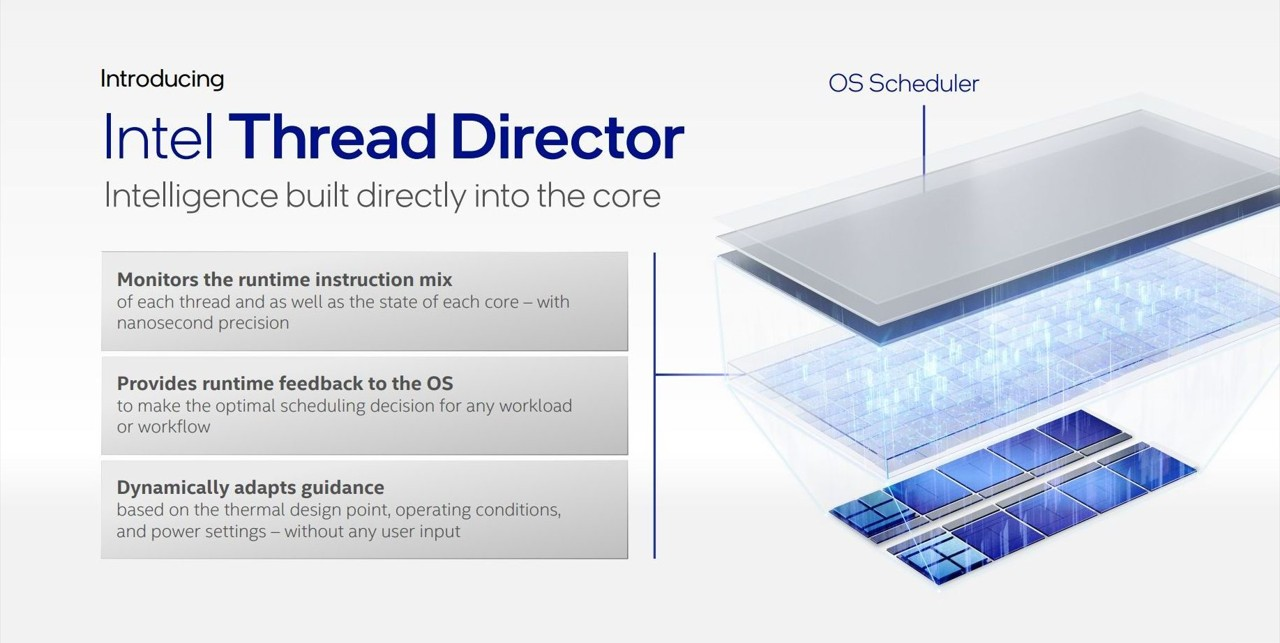
Because the 12 Gen processor adopts the Hybrid Architecture design, in order to ensure that the two cores can distribute the work in an ideal state, Intel has newly developed the "Intel Thread Director".

This technology collects the current running status and usage of each core. And provide the data to the operating system, letting the operating system make scheduling decisions.

Intel Thread Director can complete thread identification and assignment within 30µs, which is several times faster than traditional schedulers.

However, the current Win 10 operating system does not support Intel Thread Director, and currently needs to be upgraded to Win 11 to obtain the best multi-core resource allocation.

Check out MACTRON GROUP(MTG)’s new WCP Series and WMP Series. Our WCP Series will replace the processor from 8th Gen to 12th Gen early next year, which can perfectly fit all the specification upgrades of the 12th Gen processor. Take a look at this series, maybe there will be unexpected gains for you.
Friday, November 25, 2022


With the advent of Industry 4.0, AIoT is transforming our life into an information ecological chain. The central control system is the largest part of factory automation. Nowadays, most factories maintain efficacy and precision to implement highly responsive resource allocation by using CNC technology and HMI system.

When your WAM meets HMI


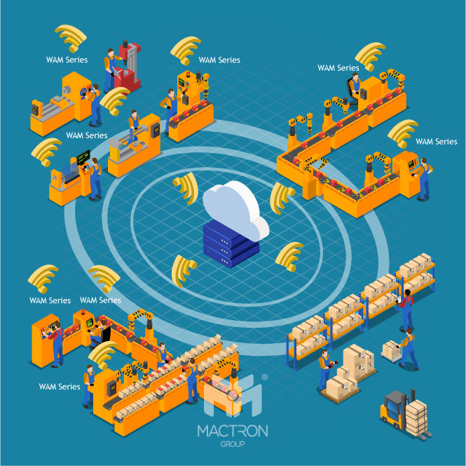
To achieve real-time monitoring, it is necessary to rely on the HMI system to achieve the purpose. The terminal data machine equipped with WAM will combine the data of each stage in the factory and transmit it to any cloud you use, whether it is AWS, GCP, or Azure.

The function of HMI


HMIs are used to optimize an industrial process by digitizing and centralizing data for a viewer. It can be used for monitoring and tracking, or for switching machines off and increasing production speed. By leveraging HMI, operators can see important information displayed in graphs, charts, and also view and manage alarms, all through one console.

Previously, operators would need to walk the floor constantly to review mechanical progress and record it on a piece of paper or a whiteboard. Now HMI technology eliminates the need for this outdated practice and thereby reduces many costly problems caused by lack of information or human error.


WAM applies to all industrialists


According to the Wirtschaftswoche in 2021, in Germany, factories that have moved to HMI systems in the past five years have reduced their manufacturing costs by about 27%, and the conversion profits are billions of euros, far beyond our imagination. This shows the combination of these devices and systems is an inevitable trend.


Check out MACTRON GROUP(MTG)’s brand new WAM Series. Our Panel Mount Touch Panel PC can adapt to all kinds of work environments with powerful performance, and combine with the HMI system. It can meet all your imagination.

Thursday, October 27, 2022


In this era of COVID-19, people now are turning increasingly to the ease of online shopping. Physical stores can no longer rely on the traditional transactional model and need to enhance the shopping experience in new ways. Self-checkout through RFID is one of the most effective ways.

How does the RFID self-service checkout system work?

1. Tag Merchandise

Retailers that introduce self-checkout systems need to attach RFID tags to all items for self-checkout purposes and to help prevent loss and returns. Staff may also use the RFID function of the Mobile Tablet PC to quickly organize product information.


2. Read Merchandise

The self-checkout system uses RFID to scan the labels on the goods, and customers only need to put the item on the counter, then approach their mobile phones or smartwatches at the payment sensor to complete the payment. If there is any problem in the payment process, they can also use their cards to check out at the end screen.

3. See Merchandise

Retailers can integrate all RFID-tagged products through AIoT, and then analyze data such as inventory and sales status to improve operational efficiency and customer experience.


RFID Self-Checkout is for any industry


According to a report from Duke University. Walmart generates nearly $1.5 billion in profits annually from self-checkout systems. However, the technology isn't exclusive to big corporations. As technology has evolved, RFID deployment has spread into new fields, now even independent clothing stores or convenience stores can see profits and growth through this technology.


Want to take a big step forward in the self-checkout system? Check out MACTRON GROUP(MTG)’s DRS Series & MCA Series. Our Touch Panel PC & Mobile Tablet PC supports various functions, such as RFID, NFC, MSR, and Barcode Scanner for all your needs.